 |
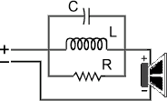
Parallel Notch Filter Circuit |
 |
Explanation of Terms |
 |
C is the capacitor value required for your filter. |
 |
L is the required inductor value for your filter. |
 |
R is the desired resistor value for this filter. |
 |
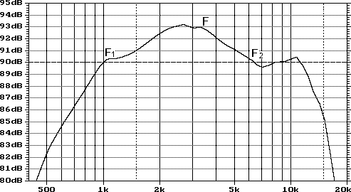
F is the frequency (in Hertz) halfway between F1 and F2. |
 |
F1 is the frequency point below F that is -3dB SPL relative to F. |
 |
F2 is the frequency point above F that is -3dB SPL relative to F. |
 |
For the example driver below, the center point of the response peak (F) would be at about 3583 (Hertz). F1 and F2 would be located at approximately 1015 and 6150 respectively.
|
 |

Frequency Response Example |
 |
At first glance, the response of the speaker above does not look like a very good candidate for a driver in a quality loudspeaker system. A broad peak in the frequency response of a speaker like the example above can be easily corrected through the use of a notch filter, however. |
 |
 |
 |
Note : This filter can be used on any type of speaker, it is not only for midranges - this was just an easy example to model. |
 |
 |
 |
If you need some logarithmic paper to aid in your SPL measurements, I have made two graphics to help. The first one can be used for low frequency plotting, and the second is a full-range scale. Just click the link for the one you need, and press the "print button" on your browser after the image is done loading. I will add some notes about the methods used to properly measure frequency response as soon as I can. |
 |
 |
Calculate Your Notch Filter |
 |
To use this form, enter F, F1, and F2. Then, click the "Calculate Values" button, and your results will appear in the empty text boxes.
|
 |
Enter F Hertz Hertz
Enter F1 Hertz Hertz
Enter F2 Hertz Hertz |
C = Microfarads
L = Millihenries Millihenries
R = Ohms Ohms |
 |
 |
|