 |
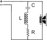
Series Notch Filters A series notch filter can be used to control the impedance peak present at the resonant frequency (Fs) of a speaker. For an explanation of loudspeaker impedance and passive crossovers, click here. If your driver has Ferrofluid in the voice-coil gap, this circuit will not be beneficial because the peak at resonance is controlled mechanically.
A high-pass crossover with a corner frequency (the frequency utilized in the crossover network design) less than two octaves above the resonance of the driver will not function properly. All crossover design formulas are accurate only when the loudspeaker impedance is at the level specified in the formula. If the impedance is higher/lower than the value used in the formula, the filter roll-off is affected.
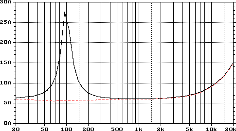
The black line in the image below shows the impedance curve of a speaker in a closed box. The red line shows the impedance of the same speaker/enclosure combination with a properly designed series notch filter.

The upward curve at higher frequencies is caused by the voice-coil inductance and is corrected using a Zobel or parallel notch filter.
When you design a crossover from a formula and apply it in a situation similar to the one above, the results are less than spectacular.
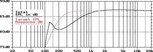
For this simulation, I modeled a driver whose resonant frequency (Fs) is 53 Hz. The component values were determined using 8 ohms for impedance and 200 Hz for the crossover frequency.
This frequency was chosen so it would be close enough to the resonance of the driver that the crossover would be affected by it.
The following image shows the desired response for a second-order Linkwitz-Riley crossover network in red. The black curve is the response you would obtain if you used the components specified by the crossover design formulas without impedance correction.

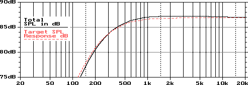
The third graphic shows how much closer to the desired response you will get by correcting the impedance of the driver.

The crossover filter goes in the circuit before the notch filter (closer to the source).
The Formulas
 |  |  | C is the value for the capacitor
L is the value for the inductor.
R is the value for the resistor. |  |
|